BUILDING AN ALARM CLOCK WITH TWO ARDUINOS
Waking up in the morning often makes me envy the dead. While they rest peacefully, I'm forced to leave the comfort of my bed to take on the day. Many people have a habit of setting an alarm and constantly hitting the snooze button when it's time to wake up. Others turn off their alarm but lay in bed for a while before getting ready. I used to be a part of the latter group. It's a bad habit to have and I knew I needed to break it. This is what compelled me to build an alarm clock... with a twist.
I needed to somehow force the user to leave their bed when it’s time to wake up. In order to make that happen, I brainstormed a few ideas:
- Attach a water gun to an Arduino and blast the user with water when it’s time to wake up.
- Add a linear actuator under the user's mattress that would tilt it and force the user off.
- Attach a T.E.N.S. unit to the alarm clock and tase the user when it’s time to wake up.
- Design the alarm clock so it only turns off if the user clicks a button in another room.
Here’s my analysis of the ideas I brainstormed:
- The water gun idea was good but would result in a wet mattress and pillow so it was scrapped.
- The linear actuator under the mattress idea sounded too dangerous since it’s forcing the user to fall to the floor.
- The T.E.N.S. unit (taser idea) sounded illegal.
- The idea to force the user to click a button in the other room to turn off the alarm accomplishes my goal of getting the user out of bed. This is what I went with.
HARDWARE
With the idea in mind, I began planning the build. Two Arduinos would make up the entire alarm clock. The first Arduino would act as the display. It will have an LCD for displaying the time and a buzzer to generate noise for when the alarm goes off. The second Arduino is going to act as the control panel. There, the user is able to snooze the alarm, turn off the alarm, or set a time (for the display or the alarm).
In all honesty, hardware is not my strong suit. I’m a software guy so programming is something I could do but building hardware with microcontrollers was uncharted territory for me. Nevertheless, I threw together these schematics to help illustrate how both Arduinos were wired.
Display Arduino:
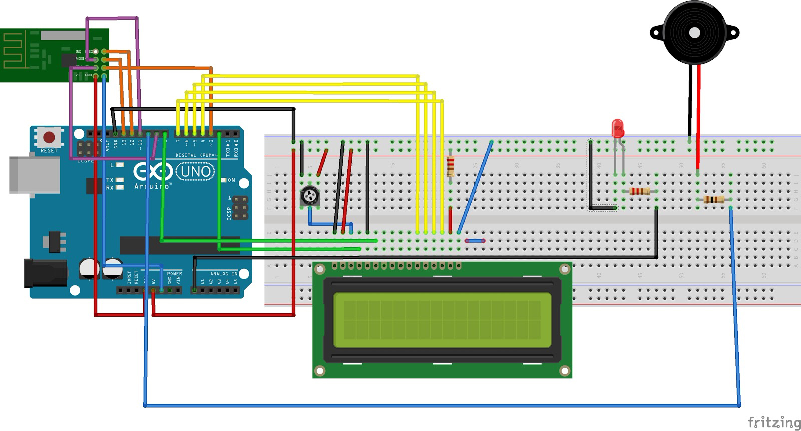
The display Arduino will be responsible for showing the time and emitting a sound when it’s time for the user to wake up.
Wiring the display Arduino required the following components:
- 1 Arudino
- 1 LCD
- 1 Piezo speaker (buzzer)
- 1 NRF24L01 transceiver module (this will be explained later)
- 1 LED
- 3 resistors
Control Panel Arudino:
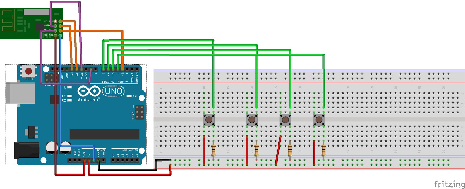
The control panel Arduino will allow the user to snooze the alarm, turn off the alarm, and set the time (for the display or the alarm).
Wiring the control panel Arduino required the following components:
- 1 Arduino
- 1 NRF24L01 transceiver module (this will be explained later)
- 4 buttons
- 4 resistors
When the display Arduino turns on, the default time shown on the LCD will be 12PM. In order to change the time, the user can use the first two buttons on the control panel Arduino. The first button will increment the time by an hour and the second button will increment the time by a minute. Pressing any of these two buttons on the control panel will change the time on the display Arduino.
To set an alarm, the user can hold the “off” button (third button) until the LCD shows “Alarm Mode.” Once in alarm mode, the user can use the first two buttons in order to set the time they would like to wake up. Once they've reached the desired time to wake up, simply press and hold the third button again in order to set the alarm and exit alarm mode. The red LED on the display Arduino will be lit if an alarm is currently set.
When the alarm goes off, the user has two options. They can either press the snooze button (fourth button), which will give them an additional 5 minutes before the alarm goes off again. Or they can press the “off” button (third button) in order to turn off the alarm.
One of the biggest challenges I faced was figuring out how to get the two Arduinos to communicate with each other. My original plan was to have them both send messages to each other via serial communication using the RX and TX pins. Serial communication is possible between two Arduinos by wiring the RX and TX pins vice-versa to each other. In other words, both Arduino’s TX pins connects with the other Arduino’s RX pins. TX and RX are abbreviations for transmit and receive, respectively. The control panel would transmit data and the display Arduino would process that data and act accordingly. The problem with this approach is that in order for it to work, both Arduinos needed to be wired to each other at all times. Having two long wires spanning from one room to another is not an elegant solution. In order to provide the user with a positive experience, I decided that the Arduinos should be able to communicate wirelessly so the user isn’t stepping over a bunch of wires while attempting to turn off the alarm.
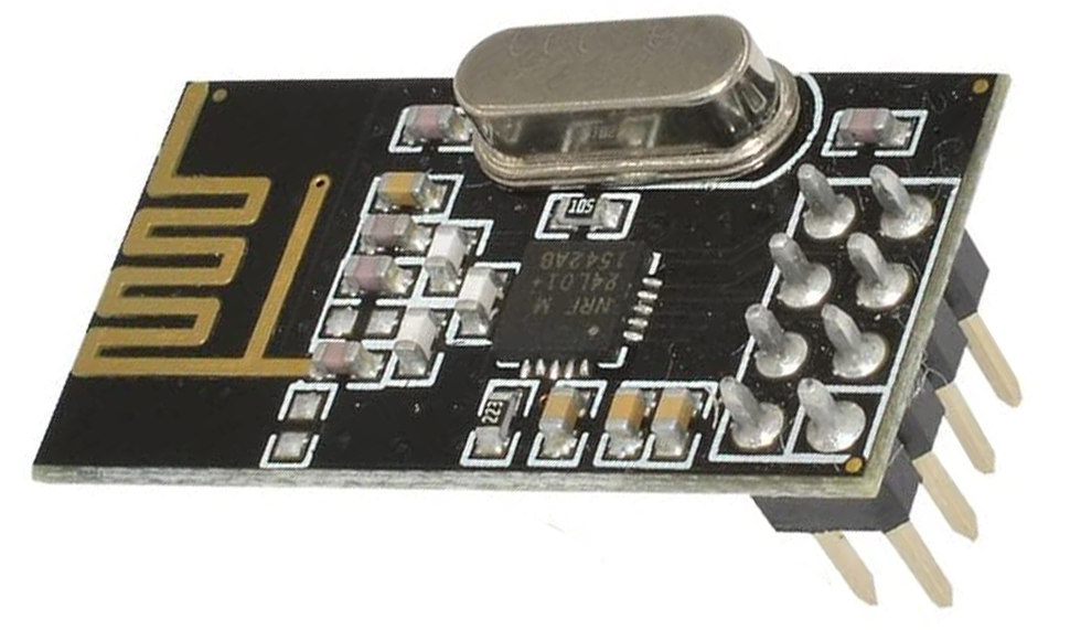
I was doing research on how I can get the two Arduinos to communicate when I discovered the existence of the NRF24L01 transceiver module. This module is able to transmit and receive data at a range of 100 meters which was perfect for what I was trying to do. Two transceiver modules will be able to handle the entire communication system for both the Arduinos. So, I purchased two NRF24L01 transceiver modules off of Amazon.
SOFTWARE
The code to allow the two modules to communicate was relatively simple thanks to the RF24 library.
Arduino Code for Display and Control Panel:
Both the display Arduino and the control panel Arduino will have the same code in the beginning.
First I created an RF24 object and passed in the CE and CSN pins that the module is wired to.
RF24 radio(3, 9); // CE, CSN pins
Next, I defined the address where both modules will be sending and receiving data to. It’s important that both transceiver modules use the same address since they will be communicating with each other.
const byte address[6] = "00001";
From this point on, the code will be different for both Arduinos since one will be acting as the receiver and the other as the transmitter. Although two-way communication is possible with the NRF24L01 transceiver modules (by constantly switching the roles of receiver/transmitter), that feature is not necessary for this project.
Control Panel Arduino Code:
In the setup() function for the display Arduino, I initialize the RF24 object by calling radio.begin(). Next, radio.openWritingPipe(address) opens the writing pipe to the address defined above. Finally, we tell the RF24 object to stop listening because the control panel will not be receiving any data. It will only be transmitting data to the display Arduino.
void setup() {
    Serial.begin(9600);

    // Open radio to allow sending commands
    radio.begin();
    radio.openWritingPipe(address);
    radio.setPALevel(RF24_PA_MIN);
    radio.stopListening();
}
Now that the Arduino is ready to begin sending commands, I defined a function called sendCommand(String command) which will transmit the command string passed as a parameter through the pipe. The function begins by converting the command string into a char array. This is done because the string needs to be converted into an array of bytes before being sent through the pipe. When the string is converted, radio.write(&text, sizeof(text)) is called and the byte array is sent for the display Arduino to read it.
// Sends a command through radio to the display Arduino
void sendCommand(String command) {
    char text[command.length()];
    command.toCharArray(text, command.length()+1);

    radio.write(&text, sizeof(text));
    delay(1000);
}
In each iteration of the loop, we constantly check if any of the four buttons were pressed. If any button was pressed, the appropriate command is sent to the display Arduino.
void loop() {
    if(isButtonPressed(upButtonHour)) {
        sendCommand("UP_HOUR");
    } else if(isButtonPressed(upButtonMinute)) {
        sendCommand("UP_MINUTE");
    } else if(isButtonPressed(snoozeButton)) {
        sendCommand("SNOOZE");
    } else if(isButtonPressed(offButton)) {

        // Delay for 500ms and read button status again to detect if the button
        // was held down
        delay(500);
        bool enterAlarmMode = isButtonPressed(offButton);

        // If the off button was held down
        if(enterAlarmMode) {
            sendCommand("ALARM_MODE");
            delay(1000);
        } else {
            sendCommand("OFF");
        }
    }
}
Display Arduino Code:
In the setup() function for the display Arduino, I initialized the RF24 object. Next, radio.openReadingPipe(0, address) opens the reading pipe to the address defined above. Finally, we begin listening in order to receive any data that the control panel Arduino transmits.
void setup() {
    Serial.begin(9600)

    //Setup Radio to begin listening
    radio.begin();
    radio.openReadingPipe(0, address);
    radio.setPALevel(RF24_PA_MIN);
    radio.startListening();
}
Now that the transceiver module is ready to begin listening to commands, I defined a function called readCommand() that returns all the data that was sent by the control panel Arduino. radio.available() returns true if there is new data in the buffer which needs to be read. If that condition is true, the read() function stores the data into the ‘text’ char array and returns.
//Reads the command sent by the control panel Arduino
String readCommand() {
    char text[32] = "";

    //If a packet was received by the control panel
    if (radio.available()) {
        radio.read(&text, sizeof(text));
    }

    return text;
}
In each iteration of the loop for the display Arduino, the readCommand() function is called and performs the necessary actions based on what command the control panel Arduino transmitted.
void loop() {
    String command = readCommand();

    if(command.equals("UP_HOUR")) {
        moveTimeUp(3600) // 3600 seconds = 1 hour

    } else if(command.equals("UP_MINUTE")) {
        moveTimeUp(60);

    } else if(isAlarmSet() && command.equals("SNOOZE")) {
        snooze();

    } else if(isSoundEmitting() && command.equals("OFF")) {
        turnOffAlarm();

    } else if(command.equals("ALARM_MODE")) {
        enableAlarmMode();
        digitalWrite(alarmModeLED, HIGH);

    } else {
        displayTime(currentTime);
        delay(1000);
    }
}
Turning off my alarm and laying in bed was not a good habit to have. With this new alarm clock fully set up, I was determined to break my horrible sleeping habit. I put the display Arduino on my nightstand and the control panel outside my door.
The first few days using this alarm clock were miserable. I felt like Frankenstein regretting his horrible creation. Although the alarm clock wasn’t a monster, it felt like one. Nevertheless, I continued moving forward and before I knew it, I conditioned myself to get out of bed immediately as soon as I heard the alarm go off.
Thank you for reading.